Sheet Metal Drawing: Process, Materials, Design & Draw Ratio
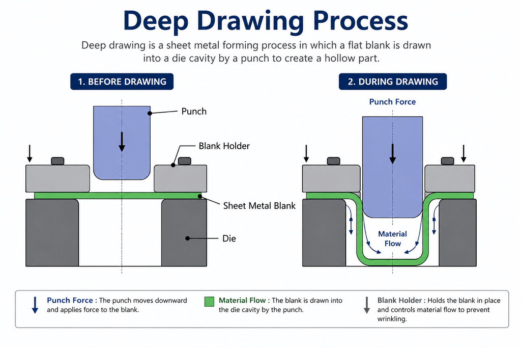
Sheet metal drawing is one of the most commonly used production processes. A flat metal sheet is pressed into a cavity by a punch, which creates a hollow part while keeping an even sheet thickness all around the part.
Introduction to Sheet Metal Drawing
Sheet metal drawing is a forming process used to create hollow components from flat blanks. Deep drawing is a common form of sheet metal drawing used when substantial material flow is required to produce deeper geometries.
The process is used to make a wide range of things that you use in your daily life, without knowing it. The products range all the way from kitchen sinks and tin cans to fuel tanks in the automotive industry.
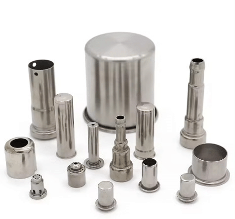
Deep drawn sheet metal stainless steel parts
The consistency of the procedure has boosted its adoption worldwide. The process allows you to make products with high-dimensional accuracy in large volumes, which is useful for mass manufacturers that demand precision.
A key feature of deep drawing is the controlled inward flow of material from the flange. During this movement, the flange experiences radial tensile stress and circumferential compressive stress, which must be controlled to prevent tearing or wrinkling.
Learning sheet metal drawing is a critical prerequisite to accurately translating design dimensions, tolerance requirements and geometry specifications into on-site process parameters.
To successfully produce parts using this process, you need to carefully control the blank holder force while also incorporating proper lubrication and draw ratios.
Understanding the Drawing Process
1. Blank Preparation
A piece of a flat sheet that is large enough for the part or component is cut to make a blank. The blank is cut using blank dies or water jets so that you get a piece with accurate dimensions.
The way to calculate blank diameter is to use the following formula: D = √(d² + 4dh)
where D = blank diameter, d = shell diameter, h = shell height (for cylindrical cups; more complex formulas apply for non-cylindrical shapes).
The blank size and shape should be calculated carefully to provide sufficient material flow without unnecessary trim allowance. Earing is influenced primarily by the planar anisotropy of the sheet material, while improper blank dimensions can contribute to inefficient material flow and forming defects.
2. Positioning and Lubrication
The blank is centered and positioned over the die cavity. Since the process involves high friction and resistive forces on both sides of the blanks are lubricated and waxed to reduce friction at the punch nose. Friction coefficients below 0.05–0.10 are often required for severe draws.
3. Blank-Holder Clamping
The blank is held in place with the help of a pressure cushion or hydraulic system, which evenly distributes force on the workpiece. The blank holder force applied depends on your choice of material and typically can range from 0.5- 3 MPa. using variable BHF, which pulsates or applies force at an angle, minimizes wrinkles in the workpiece while allowing proper material flow.
4. First Draw (Cupping)
The process starts with the punch lowering to push the blank into the die. As the punch moves into the die, material from the flange flows inward beneath the blank holder and over the die radius to form the cup wall.
The limiting draw ratio (LDR = D/d) for most steels in the first draw ranges from 1.8–2.3; aluminum and brass typically 1.7–2.0.
5. Redrawing (Subsequent Draws)
The first draw is only capable of giving a limited amount of height to the component. This means that if you want to create a taller component, you need to perform redraws to increase the wall height.
The maximum draw ratio you can achieve across the multiple stages can reach 4–6 for steels and 3-4 for aluminum.
6. Ironing (Optional)
Ironing is a technique that is used to create parts with tighter tolerances and smoother surface finishes. In this process, you set the clearance of the punch to die lower than the thickness of the sheet (typically 70-90 % of the initial thickness) to forcibly create thinner walls.
7. Trimming and Finishing
This is the last touching step in which the open end is trimmed to clean it up and give a finished and clean appearance. Additional operations such as flanging and necking are used depending on the requirements.
Cold Drawing and Its Variants
Conventional Deep Drawing
Conventional deep drawing is done at room temperature and typically uses round or rectangular punches. The majority of production applications use this technique to create high-quality parts and components.
Reverse (or Redraw) Drawing
In reverse drawing, you turn the cup and redraw over a small punch in the opposite direction to reduce wall thinning at the front of the punch. This allows you to reach a higher total depth, creatinga part that has higher walls without compromising the dimensional stability.
Direct Redrawing
The second draw is done right after the initial draw in the same direction. It is faster, but its speed of the process is limited by the thinning of the bottom radius.
Ironing-Drawing Combinations
Sequential drawing followed by one or more ironing stages is used to produce tall, thin-walled containers by gradually shaping and then thinning the metal. After the initial draws form the basic cup shape, the cup is pushed through a series of ironing rings that reduce the wall thickness while maintaining the original diameter.
Hydroforming and Hydromechanical Drawing
This process involves filling the die cavity with pressurized fluid, which is then pushed by the punch to force the sheet metal against the walls of the die. The process has a better material flow that distributes pressure evenly, which allows for higher draw ratios.
Warm Drawing (200–400 °C)
Warm drawing is different from other drawing procedures. It is used for magnesium and advanced high-strength steels that are easier to work with and form at high temperatures.
The higher temperature reduces the flow stress and improves the ductility of the material, allowing you to make complex geometries that are next to impossible at room temperature.
Material Considerations for Sheet Metal Drawing
Drawability is governed by normal anisotropy (r-value) and strain-hardening exponent (n-value). Higher average r̄ (>1.4 for steels, >0.8 for aluminium) promotes wall strength and reduces thinning. Materials commonly used:
- Low-carbon steels (DC04, DC06): r̄ ≈ 1.8–2.2, excellent drawability.
- Stainless steels (304, 430): moderate r̄ (0.9–1.3), higher strength requires higher BHF.
- Aluminum alloys (5182, 6061): lower r̄ (0.6–0.8), pronounced planar anisotropy causes earing.
- Copper and brass: good ductility, low strength.
- Advanced high-strength steels (DP600–DP1180): lower elongation, require warm forming or servo-press technology.
- Titanium (CP-Ti, Ti-6Al-4V): poor cold drawability, typically drawn warm or hot.
Thickness uniformity, surface quality, and grain size also influence fracture location and wrinkling tendency.
Design Considerations for Sheet Metal Drawing
- Keep an even wall thickness throughout the piece and avoid a sudden change in shape. The change should be gradual to avoid sharp edges that can cause tears.
- The filler and corner radius must be greater than 4–10 × sheet thickness. This is because small radii cause thinning and tearing of the sheets.
- The draw depth of a single stage should be kept at 60-70% of the part’s diameter. If you need more depth you can redraw after properly planning it.
- You can incorporate drawing angles from 5–10°, making the part release easier.
- The should be a proper flange for the blank holder contact.
- Similar to bending to account for the spring back, you need to over-bend using a draw bead so that the part has an accurate shape.
- Locate side piercings or holes after drawing to prevent distortion.
- Symmetrical geometries generally simplify material-flow control and tooling design, while asymmetric parts can create uneven material flow and require more complex blank and tooling optimization.
- The blank-holder requires draw beads or lock beads to manage material flow and prevent wrinkle formation.
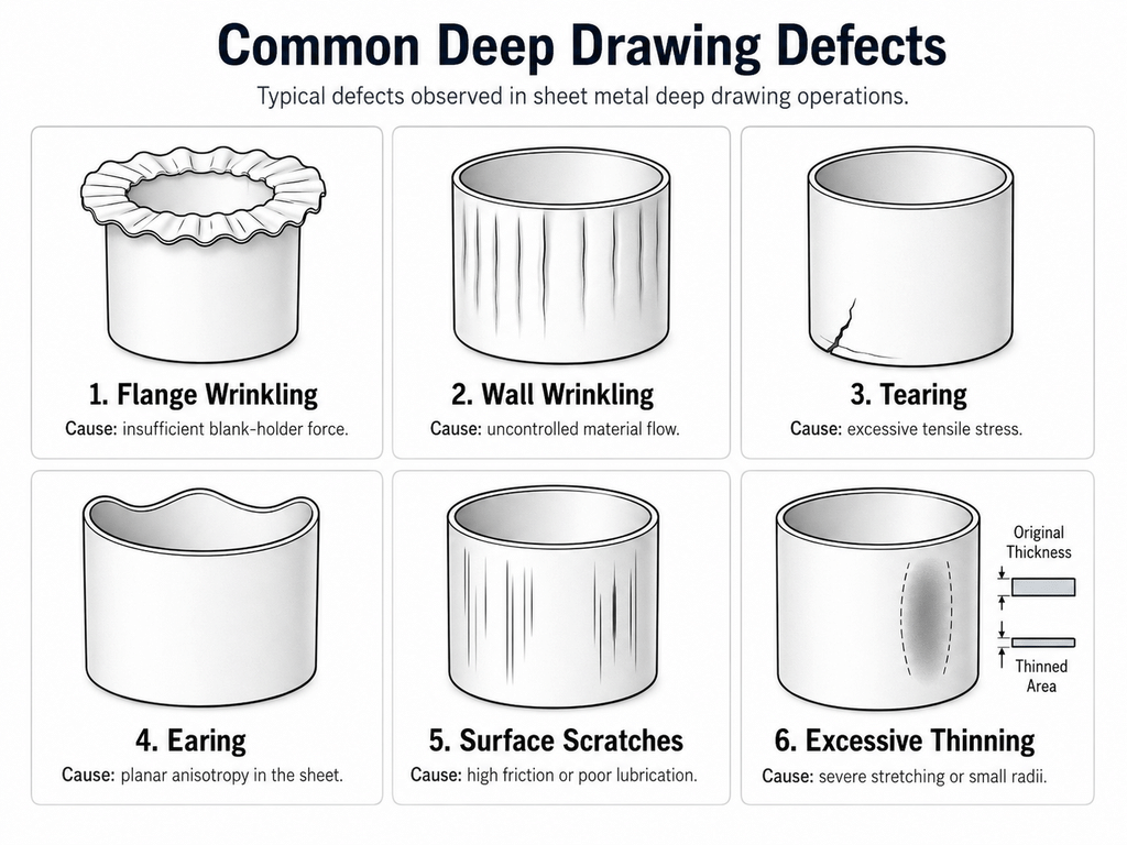
Deep drawing common defects
Flat Pattern and Bend Details
Deep-drawn parts are made from flat patterns. This means that the initial part starts as a flat piece of metal and is slowly shaped and curved into its final form. To calculate the most accurate blank, you need to know certain values and parameters:
Surface area constancy: Total surface area of blank = surface area of final part + trim allowance.
For cylindrical cups: D = √(d² + 4dh + 2πr(d + 2h/3)) (approximation including radius effects).
Commercial software (AutoForm, Dynaform, Pam-Stamp) uses finite-element inverse methods to predict optimal blank shape and thinning distribution.
The Bend allowance concepts do not work for deep drawing because the material deformation happens through plane strain instead of bending. Standard bend allowance formulas apply to bending operations which follow the drawing processes when flanges are involved in the production of the part.
L = (π/180) × R × α + k × t
where R = inside radius, α = bend angle, k = neutral axis factor (≈0.33–0.50).
Conclusion
As a core process within sheet metal fabrication,sheet metal drawing continues to be an efficient manufacturing method that creates strong, lightweight components without seams. The process requires complete material anisotropy analysis together with various other parameters such as friction control and blank-holder force management. The whole process takes multiple tool stages to design and reach the target draw ratios without thinning and fracturing.