Sheet Metal Drawing: Process, DFM Tips & Software
Sheet metal drawing is a useful technique for shaping flat metal sheets into useful shapes. It is used to create parts such as boxes, panels, and machine enclosures. It uses punches and dies to shape the metal, requiring careful control of pressure and movement. You can achieve curves and precise sizes to ensure parts fit perfectly in their final assembly. Sheet metal drawing is a practical and widely used technique in various industries, including aerospace, automotive, and electronics.
What Is Sheet Metal Drawing?
Sheet metal drawing involves forming flat metal sheets into 3D shapes. A punch and die form the metal by pulling it into a desired configuration without tearing it. It is used to make parts, such as kitchen sinks, automobile bodies, machinery covers, storage cases, and industrial enclosures.
The depth, curve, and angle of individual parts are controllable by the designer, ensuring that all parts fit together in the desired assembly. The common deep-draw materials are steel, aluminum, brass, and copper. It allows for close control of thickness, edges, and smoothness. If properly planned and executed, you can reduce material waste and avoid cracks or wrinkles in the finished product. The process is suitable for both large and small-scale quantities.
Deep Drawing Manufacturing Process Steps in Sheet Metal Fabrication
Deep drawing is a sheet metal working process used to produce hollow or recessed parts, such as cups, cans, automobile fenders or panels, casings, and more. The metal is drawn without tearing it. The steps are:
Selection of Material
A suitable sheet metal, such as steel, aluminium, or stainless steel, is chosen. This material should be of good ductility and uniformity of thickness so that it will not crack during drawing.
Preparation of Blank
The sheet metal is cut into flat circular blanks. The size of the blank depends on the final size of the part to be produced, taking into account factors such as depth and diameter. Edges should be smooth to avoid tearing. The blank should be circular in shape.
Die and Punch
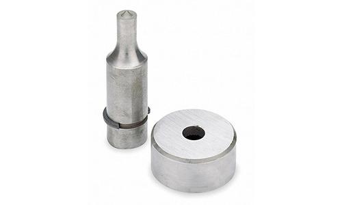
The die and punch are installed in the press. The die determines the final shape, while the punch forces the metal into the cavity of the die. They must be properly aligned. Otherwise, wrinkles or uneven stretching of the metal will appear.
Lubrication
Lubricant is applied to the blank to reduce the friction between the sheet and the die. Lubrication enables a smooth flow of the material and minimises scratches or tearing.
Drawing Operation
The punch forces the blank into the cavity of the die. The metal is stretched and formed into the proper shape. At this stage, the process may require several stages to create deep parts and prevent tearing.
Redrawing if Necessary
For parts where the depth-to-diameter ratio is critical, several redraws are performed. With each redraw, the diameter is decreased a little, and the depth increased. This is done to prevent excessive thinning or cracking.
Trimming and Finishing
Once the drawing has been completed, the excess on the edges is trimmed to the required size. Depending on the drawing, other operations may be performed with it, such as Piercing, Hemming, coining, etc.
Key DFM Considerations for Sheet Metal Drawings
The design of sheet metal parts requires careful consideration to ensure smooth, economical, and dependable production. If sufficient thought is given to manufacturability at the outset of the work, time will be saved, mistakes will be avoided, and the parts will work as intended.
Map out the Manufacturing Steps
Before you start drawing, think about how the part will be made. Will it be cut, bent, drawn, or formed? Check the machine’s capabilities and limitations for the desired material type and thicknesses. Specific applications, such as deep draws or tight internal corners, may require special tools or additional operations. The careful planning of each step will result in designs that can be made more readily and decrease the chance of excessive delays in production.
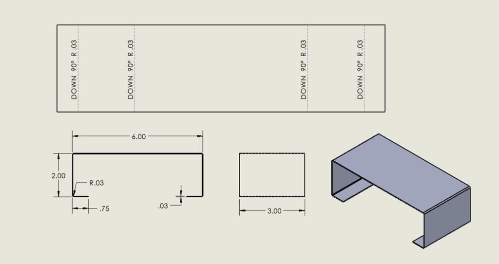
Flat Pattern Designs
The flat patterns are those in the two-dimensional form prior to production. The first consideration is whether the blank sizes make full use of the materials, thereby minimising scrap.
Next, consider the locations of holes, cutouts, or other areas where there may be a risk of wrinkling or tearing the metal during the forming process. For instance, holes too close to an edge may cause it to crack during secondary bending operations. Poor flat patterns may result in inaccurate parts and excessive scrap due to waste.
Bending Designs
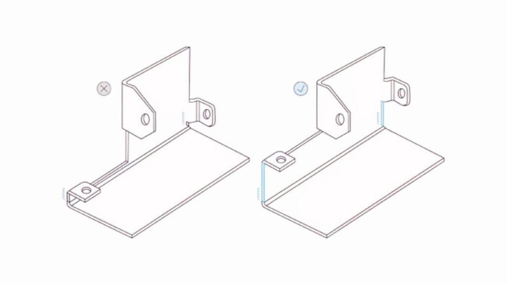
The bends are critical to fit and strength. For all bends, calculate the offset and springback, including the material type and thickness. Proper radii should be employed, as sharp bends in thick steel may crack during subsequent work, while the greater radii keep all material strong.
Bends should not be placed too close to holes, edges, or other bends in the work, as these factors can make proper bends difficult, thereby requiring both the right shape and fit, while minimising scrap from mistakes.
Set Allowable Tolerances
Tolerance is an allowance that is permitted above or below the actual dimensional value. Set realistic values for the tolerances. It is usually based upon the materials employed, the thickness, and the types of operations. Too tight a tolerance will increase the costs and production difficulties, while too loose will cause trouble with assembly. Emphasising essential characteristics, such as hole position, bend location, and mating surfaces, will help ensure the proper function and fit of the parts.
Sheet Metal Drawing Software
Here are the common software used in Sheet Metal Drawing
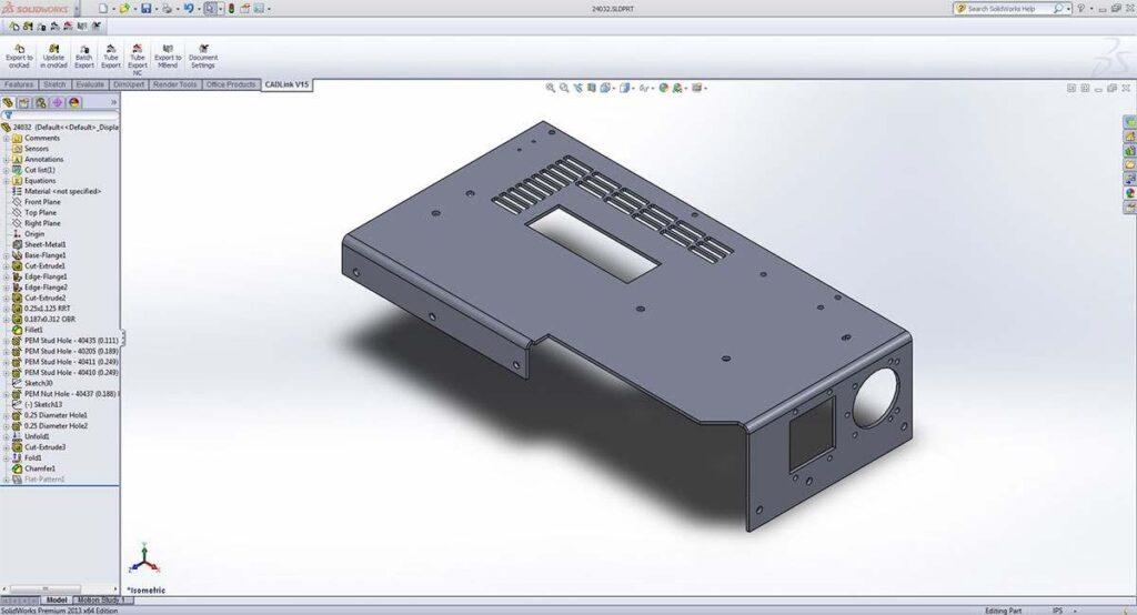
SOLIDWORKS
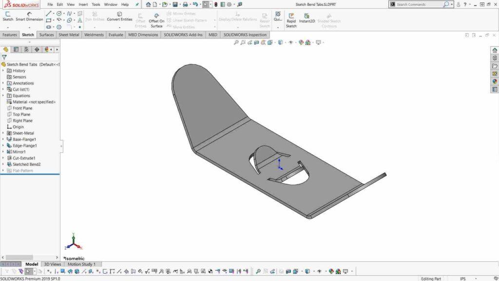
SOLIDWORKS enables the creation of 3D sheet metal parts and automatically generates flat patterns. Bends, flanges, and complex shapes can be easily added to the parts. It has become widely used by much of the industry, as it has virtually eliminated the errors and time involved in transitioning from the design process through manufacture.
Alibre Design
Alibre Design has a set of straightforward programs for the sheet metal drawing process. It can convert solid parts into sheet metal parts, produce 3D models, and produce flat patterns. This is a suitable program for engineers who require precise control over parts and drawings without unnecessary complexity.
Onshape
Onshape is a cloud-based CAD software. It allows users to create parts, unfold them, and generate flat patterns for manufacturing. The teams have the opportunity to collaborate in real-time, making it particularly useful when multiple designers work on the same project.
Solid Edge
Solid Edge provides specialised functions for sheet metal, including automatic flat patterns, bend tables, and drawings optimised for manufacture. It is optimum for companies that want an easy transference from design to production.
cncKad by Metalix
cncKad is a specialised sheet metal drawing software for 2-D and 2.5-D aspects. It is superior in detailing holes, notches, and chamfers.
Summary
Sheet metal drawing allows you to turn flat sheets into functional products/parts. However, it requires careful planning of the bends, holes, and measurements so that the parts fit well and minimise waste. Selecting the right material and utilising the proper tools and software makes the process easier.